

Virtual pinball setup guide 2026
Build, install and tune a serious VPX cabinet
A complete, current guide to VPX, PinUP Popper, VPinMAME, FlexDMD, B2S, DMDext, DOF, cabinet parts, wiring, displays, downloads and cabinet build planning.
Use the Retrocade live virtual pinball table database to find VPX tables, backglasses, PuP Packs, ROM notes, media packs and public source links.
Release links and version references checked against official GitHub/NailBuster sources on 25 June 2026: VPX 10.8.0, PinMAME 3.6, B2S Server 2.1.6, DMDext 2.5.0, FlexDMD 1.9.1 and DOF R3++ 3.2.1.
Pinscape-style cabinet build manual
Start at the wood, finish at DOF
This version follows the structure of MJR’s Pinscape Build Guide: plan the cabinet, make it serviceable, mount displays, ground the metalwork, install the PC, wire controls, add plunger/nudge, then add feedback power and DOF toys. Do the steps in order. Do not start with Popper playlists or solenoids.
2. Buy parts
3. Build shell
4. Mount displays
5. Grounding
6. PC and Windows
7. Software
8. Buttons
9. Plunger/nudge
10. DMD
11. Audio/SSF
12. Feedback power
13. DOF
14. Toy wiring
15. Fuses/diodes
16. Tables
17. Testing
1. Decide the exact cabinet before buying anything
A virtual pinball cabinet is a physical machine first and a software install second. Start by choosing the cabinet class, because every later choice depends on it: screen size, cabinet width, button position, plunger clearance, PC/GPU, DMD type, Popper display layout, DOF output count and service access.
Write this build sheet first
- Cabinet type: desktop, two-screen, three-screen, full-DMD LCD or real DMD.
- Playfield display size, real outside dimensions, native resolution and refresh rate.
- Backglass display size and whether the backbox will use real speakers and a speaker/DMD panel.
- DMD choice: virtual window on backglass, full-DMD LCD, PinDMD/Pin2DMD-style hardware or another real-DMD device.
- Controls: flippers, magna-save, start, exit, coin/credit, launch button, real plunger, service buttons and coin door switches.
- Feedback: none, SSF only, basic contactors, or full DOF with contactors, shaker, gear motor, fan, flashers, strobes and addressable LEDs.
- Service plan: how the playfield opens, how the backbox opens, where fuses live, and how you will reach the PC after the cabinet is built.
Checkpoint: you can draw the cabinet side view, backbox view and internal electronics bay before buying parts.
2. Buy parts in the order that prevents expensive mistakes
The Pinscape approach is to lock down the mechanical dimensions before the electronics. The playfield display, lockdown bar, side rails, glass/acrylic, backbox screen and speaker/DMD layout decide the cabinet dimensions. Buttons, boards and toys can be moved later; a screen that does not fit cannot.
| Buy/choose | Why first | Specific check |
|---|---|---|
| Playfield display | Sets body width/depth and GPU requirement. | Measure the actual bezel/case, not just advertised diagonal size. |
| Lockdown bar and glass/acrylic | Sets the front opening and top trim. | Confirm width against cabinet body before cutting wood. |
| Backglass display | Sets backbox width/height and mounting depth. | Leave room for speakers, DMD panel and cable exits. |
| DMD/full-DMD hardware | Changes speaker panel and software layout. | Decide LCD vs real DMD before cutting the panel. |
| Controller board | Determines input count, plunger/nudge support and output options. | Check support for analog plunger, accelerometer and DOF outputs. |
| Feedback power/driver system | Determines fuses, wire routing and service bay space. | List toy voltage/current before buying supplies and drivers. |
Controller choices to research before drilling
- Pinscape/KL25Z: classic Pinscape platform with detailed documentation, but older KL25Z assumptions may not match every newer board revision.
- Pinscape Pico/PicoScape-style projects: modern Pico-based direction for DIY controls and Open Pinball Device-style workflows.
- Arnoz ecosystem: ready-made Pinscape/KL25Z-style boards, MOS boards, plunger parts and cabinet electronics; check compatibility before mixing systems.
- Keyboard/joystick encoders: acceptable for basic buttons but not a complete cabinet solution if you want analog plunger, nudge and DOF toys.
3. Build a serviceable cabinet shell
A cabinet that cannot be opened and repaired will punish you later. Build it so the playfield can lift or slide, the backbox can be opened, the PC can be reached, fuses can be changed, and every controller board can be unplugged without cutting wires.
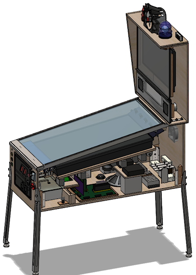
Build procedure
- Cut or assemble the body only after you know the playfield display outside dimensions and the lockdown-bar width.
- Dry-fit the playfield display before paint/wrap. Confirm clearance around the bezel, front buttons, plunger body and cable exits.
- Create a service opening or lift/slide playfield strategy before mounting electronics underneath.
- Plan an electronics bay: PC, USB hub, controller, output boards, fuse blocks, power strips and DC power supplies.
- Keep mains AC wiring in protected areas and separate from low-voltage button/sensor wiring.
- Install cable tie points or wire ducts before the cabinet fills up.
- Leave slack/service loops so the playfield or backbox can open without ripping connectors out.
4. Mount the playfield, backglass and DMD correctly
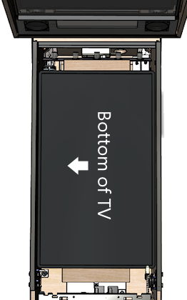
The playfield screen should run lengthwise from the player end toward the backbox. The front of the virtual table should be at the lockdown-bar/player end; the rear of the table should be toward the backbox. If the diagram or screen orientation is sideways or reversed, fix the physical/Windows orientation before software setup.
Playfield mounting steps
- Remove unnecessary TV stands/brackets only after confirming the screen still powers on and has accessible buttons/IR if needed.
- Mount the display on rails, shelf supports or a liftable platform so it cannot shift during nudging.
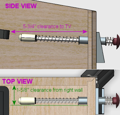
- Leave clearance for the plunger rod and launch button area. Pinscape specifically calls out plunger-to-TV conflicts as a planning issue.
- Route HDMI/DisplayPort and power cables so lifting the playfield does not strain the connectors.
- Test the screen in the cabinet with glass/acrylic in place before final trim.
Backbox and DMD mounting steps
- Mount the backglass display so it can be removed later from the rear or front.
- Cut speaker holes and DMD/full-DMD opening after confirming the actual panel dimensions.
- If using a full-DMD LCD, check controller-board clearance behind the panel.
- If using real DMD hardware, plan power, USB/data and ventilation before closing the backbox.
5. Ground the cabinet metalwork
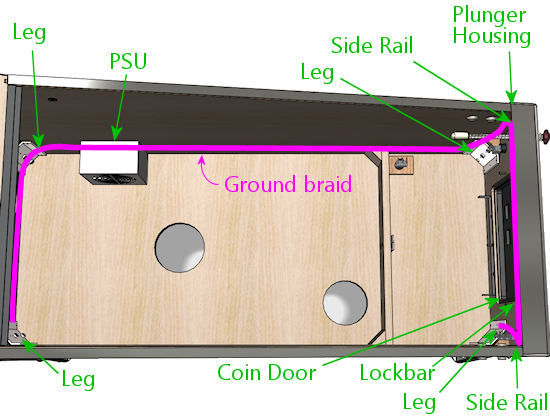
Pinscape devotes a full chapter to cabinet grounding because real pinball cabinets bond exposed metal parts to earth ground. Virtual cabinets should do the same when they use metal legs, rails, lockdown bars, coin doors and plunger plates.
Grounding procedure
- Use the earth ground from a properly grounded AC source, such as the PC power supply case/ground path or a suitable ground connection method.
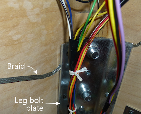
- Run ground braid or heavy ground wire around the cabinet where metal parts attach.
- Bond the leg plates, side rails, plunger plate, lockdown bar receiver, coin door and other exposed metal to the ground path.
- Use screws/bolts through braid or ring terminals so the connection is mechanical, not just a wire lying nearby.
- Keep bare braid away from live terminals and low-voltage boards.
- Use a multimeter in resistance/continuity mode and verify each exposed metal part connects to earth ground.
Checkpoint: touch one meter probe to the AC ground prong/known earth point and the other to each metal cabinet part; you should see continuity/very low resistance.
6. Install the PC, cooling and Windows
Mount the PC where it can breathe and be serviced. Do not bury USB hubs, display cables or power switches under the playfield where you cannot reach them. Pinscape’s inside-the-cabinet chapter repeatedly shows the value of shelves, lips, terminal blocks and organized power strips.
- Mount the PC or motherboard tray so the GPU fans have air and the video cables are not kinked.
- Use intake and exhaust fans to move air through the cabinet, especially around the PC/GPU and power supplies.
- Mount USB hubs and controller boards near the devices they serve but still reachable.
- Install Windows after the final displays are connected in their cabinet positions.
- Set screen orientation/order: playfield, backglass, then DMD/full-DMD.
- Use 100% scaling where possible, disable sleep/hibernate, disable USB selective suspend if boards disconnect, and use performance power mode.
7. Install software only after the display order is stable
Use PinUP Baller Installer for a clean beginner install, or manually install VPX, VPinMAME, B2S, DMDext, FlexDMD, PinUP Player/Popper and DOF. The rule is simple: install one layer, test that layer, then continue.
- Create
C:\vPinballor another short, non-OneDrive path. - Install VPX and test one non-ROM table from VPX directly.
- Install/register VPinMAME and test one ROM table with the ROM zip left zipped in
VPinMAME\roms. - Install B2S Server and test one matching
.directb2sfile beside the VPX table. - Install/configure DMDext and FlexDMD only after you know what type of DMD output your test tables use.
- Install/configure PinUP Popper after tables launch correctly outside the frontend.
- Add DOF after the output hardware and toy power system are planned.
8. Wire cabinet buttons like a real control panel
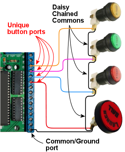
Pinscape’s button wiring chapter shows the basic pattern: each switch input goes to a controller input and a common/ground return. The exact pins depend on your board, but the workflow is universal.

Button wiring steps
- Install the flipper buttons first. Use quality leaf switches or microswitches that behave reliably at low logic voltage.
- Wire one side of the switch to a labelled input on the controller.
- Wire the other side to the controller ground/common. Use a daisy chain only if your controller documentation supports it.
- Use 24 AWG or similar light hookup wire for button/logic wiring; use heavier wire for power and high-current toys.
- Label both ends of every wire:
LEFT_FLIPPER,RIGHT_FLIPPER,START,EXIT, etc. - Test every button in the controller tool or Windows game-controller panel before mapping VPX.
- Only after basic inputs work should you add lit buttons, coin-door switches and service buttons.
9. Install plunger, nudge and tilt as separate systems
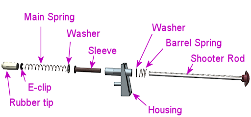
A launch button is a simple switch. A real plunger is an analog sensor plus a mechanical shooter assembly. Nudge is an accelerometer mounted rigidly to the cabinet. Treat them as three different systems.
Plunger steps
- Mount the mechanical plunger through the front panel and confirm it moves freely.
- Check clearance to the playfield display; lower or adjust the plunger if the rod conflicts with the screen.
- Choose the sensor type: potentiometer, optical/linear sensor, proximity/distance sensor or a ready-made plunger board.
- Wire the sensor exactly as the controller expects. Potentiometer-style setups usually require power, ground and signal.
- Use the controller config tool to calibrate the plunger travel.
- Test multiple tables and fix table-specific plunger scripts only after the hardware calibration is stable.
Nudge/tilt steps
- Mount the accelerometer/controller firmly to the cabinet floor or a rigid plate.
- Do not leave it hanging from USB and do not isolate it from cabinet motion; it must move with the cabinet.
- Calibrate it after the cabinet is on its final feet/legs.
- Use VPX nudge settings carefully. Over-sensitive nudge is usually worse than no nudge.
- If nudging is erratic, check mounting rigidity before changing software settings.
10. Choose and configure DMD output
Pinscape separates DMD selection from general display setup because it affects the backbox and speaker panel. Your options are: virtual DMD on an LCD, full-DMD LCD, monochrome/color real-DMD hardware, or table-specific FlexDMD/PuP output.
- If using LCD DMD/full-DMD, connect it as a normal GPU display and set Windows order/scaling before configuring PinUP or DMDext.
- If using real DMD hardware, mount the device only after testing power, USB/data and DMDext/DmdDevice output.
- For VPinMAME tables, test the DMD outside Popper first.
- For FlexDMD originals, install/register FlexDMD and read the table notes.
- For PuP DMD/full-DMD media, run PinUP display setup and choose the pack option matching your cabinet layout.
11. Add audio and SSF before heavy mechanical feedback
Audio is part of the cabinet build, not an afterthought. A common modern path is normal backbox speakers plus subwoofer, then SSF exciters mounted near front/rear cabinet zones. SSF gives physical feel without high-current coils.
- Mount backbox speakers and subwoofer first and confirm normal Windows audio works.
- Add an amp/audio interface for SSF if used.
- Mount front exciters near flipper zones and rear exciters closer to bumper/slingshot zones.
- Configure Windows speaker channels and VPX audio output.
- Test ball rolling, flippers and bumper sounds before adding contactors.
12. Build feedback power properly
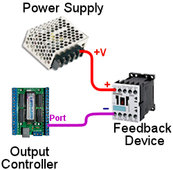
Feedback devices usually need separate DC supplies. Pinscape’s feedback wiring chapter explains the central rule: the device positive goes to the correct power supply positive, the device negative is switched through the output controller/driver, and all relevant power-supply negatives/grounds must be tied together where the controller system requires common ground.
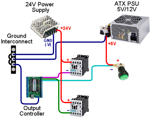
- List each toy: contactor, solenoid, knocker, shaker, fan, gear motor, flasher, strobe, LED strip.
- Write voltage and current draw for each toy.
- Group toys by voltage: 5V, 12V, 24V, 48V, etc.
- Choose DC supplies with headroom, not supplies running at their absolute limit.
- Install a fuse strategy before connecting toys.
- Use terminal blocks/fuse blocks so the wiring can be serviced.
- Do not run feedback toys from the PC USB port or directly from logic pins.
13. Configure DOF after hardware ports are known
DOF maps simulator/table events to physical output ports. Configure the cabinet in DOF after you know which output board and physical port controls each toy.
- Install DOF/DirectOutput and unblock downloaded files if Windows blocks them.
- Confirm B2S can load plugins; if the plugin/status button is unavailable, DOF is not loading correctly.
- Create/update the cabinet in DOF Config Tool.
- Assign ports to real toys using names that match your wiring map.
- Generate/download the config files and place them in the correct DOF config folder.
- Use a DOF test table or output-board utility before blaming table scripts.
- Regenerate configs any time you change output boards, toy assignments or port numbers.
14. Wire each feedback toy one at a time
Do not install ten toys and then troubleshoot all of them. Wire and test one output at a time.
Generic DC toy wiring
- Power supply positive goes to the toy positive through the appropriate fuse.
- Toy negative goes to the MOSFET/output driver channel.
- The driver board connects to the output controller/USB board according to that board’s manual.
- The relevant grounds/negative terminals are interconnected as required by the controller/driver design.
- Inductive toys get flyback diode/suppression.
- Test the output with short pulses before playing a table.
Common toys
- Contactors: good for flippers, slings and bumpers. Mount firmly to wood or brackets for a crisp knock.
- Knocker: high-current coil; needs proper driver, fuse, diode and short pulse behavior.
- Shaker motor: draws significant current and vibration; mount securely and isolate wires from moving parts.
- Gear motor: low-speed motor for mechanical rumble; wire through driver and fuse like other DC motors.
- Fan/blower: can be used for table effects; check current draw and airflow direction.
- Flashers/strobes: require correct LED resistors/driver hardware and should be aimed before final mounting.
- Addressable LEDs: need data, power injection planning and suitable 5V supply capacity.
15. Use fuses, diodes, wire sizes and MOSFETs correctly
This is where a cabinet becomes safe and reliable. Pinscape’s electronics chapters cover wire, fuses, diodes and MOSFETs because each one prevents a different failure.
Wire
- Use light hookup wire such as 24 AWG for buttons and logic signals.
- Use heavier wire for power supplies, motors, coils and long runs with higher current.
- Use a color code. Pinscape recommends starting with power rails: black for ground/0V, then consistent colors for 5V, 12V, 24V, etc.
- Label both ends even if you use colors; color alone is not enough in a 50+ wire cabinet.
Fuses
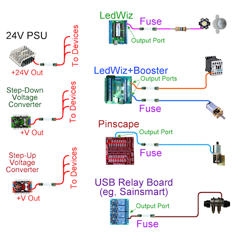
- Use fuses to protect output boards and power branches from shorts/overloads.
- Put output fuses close to the output controller/driver or fuse board so the protected branch starts there.
- Use DC-rated fuses for DC circuits, and choose voltage rating at or above the circuit voltage.
- Choose current rating based on the circuit load and board/device limits; do not randomly oversize fuses.
Diodes and MOSFETs
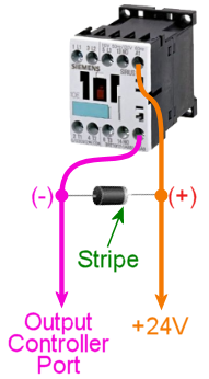
- Coils, contactors, relays, solenoids and motors create voltage spikes when switched off.
- Install flyback diodes/suppression across inductive loads unless your driver board already provides it.
- MOSFETs switch the toy current; the controller pin only controls the MOSFET.
- Choose MOSFET/driver boards rated for the toy current and voltage, with heat handling where needed.
16. Add tables one at a time
A VPX table might require a VPX file, ROM zip, directB2S, FlexDMD, DMDext settings, altcolor/colorization, music, PuP Pack and table-specific scripts. Install one complete table before the next.
- Download from the author-approved source.
- Read the table notes for VPX version, ROM name, B2S and PuP Pack requirements.
- Place the VPX table in the Tables folder.
- Keep ROM zips zipped in the VPinMAME ROMs folder.
- Match directB2S filename to the table base name.
- Test from VPX first. Add to Popper last.
- Use the Retrocade table database and VPS to cross-check table files, backglass links, PuP Packs and ROM notes.
17. Test like a builder, not like a player
Final testing should prove each layer by itself before you play for fun.
- Cold boot: cabinet powers up, screens appear in the right order, USB boards connect, audio loads.
- Controls: every button, plunger and nudge axis works in Windows/controller tool and in VPX.
- Displays: playfield, backglass and DMD/full-DMD positions survive reboot.
- Software: non-ROM table, ROM table, B2S table and PuP Pack table launch outside Popper.
- DOF: each output port fires from a test tool before table scripts are used.
- Safety: fuses are labelled, ground continuity is tested, no bare mains terminals are exposed, no wires rub moving toys.
- Frontend: only after all above pass, add Popper playlists, media and launch scripts.
Complete cabinet manual
The full virtual pinball build guide
This is the long-form build path. Treat it like a workshop manual: make decisions in order, test each layer, and do not add the next subsystem until the current one works.


Build order: do these steps in this order
- Choose the cabinet class: desktop, two-screen, three-screen, full-DMD LCD or real DMD.
- Choose the playfield display size before choosing cabinet width.
- Choose backglass and DMD/full-DMD screen sizes before building the backbox.
- Decide whether the cabinet will have plunger, nudge, SSF, DOF toys or real DMD.
- Buy layout-defining parts first: screens, lockdown bar, legs, glass/acrylic and cabinet shell materials.
- Build the cabinet shell, backbox, service access, cooling path and screen mounts.
- Mount the screens temporarily and confirm physical fit before permanent wiring.
- Install Windows, GPU drivers and all displays in their final order.
- Set power mode, scaling, screen orientation and cabinet folder structure.
- Install the virtual pinball software stack from the official sources.
- Test one non-ROM VPX table directly from VPX.
- Test one ROM table with VPinMAME and a zipped ROM.
- Test one directB2S backglass outside Popper.
- Set up virtual DMD, full-DMD LCD or real DMD and make the position survive reboot.
- Wire cabinet buttons and prove every input in Windows and VPX.
- Add plunger and nudge, then calibrate after the cabinet is assembled.
- Add SSF audio if used, then test channels and exciter placement.
- Add DOF outputs one at a time using fuses, drivers and a wiring map.
- Add tables one at a time: VPX file, ROM, B2S, PuP Pack, media and Popper entry.
- Back up the working install before changing versions or adding bulk tables.
1. Decide what kind of virtual pinball machine you are building
There are several very different projects that people call “virtual pinball”. A desktop VPX setup is software-first: one monitor, keyboard or gamepad controls, no cabinet wiring. A two-screen cabinet uses a playfield display and a backglass display; the DMD is usually placed on the backglass. A three-screen cabinet adds a dedicated DMD or full-DMD LCD. A high-end cabinet may include real pinball parts, a real DMD, analog plunger, accelerometer nudge, surround sound feedback, solenoids/contactors, shaker motor, gear motor, fan, flashers, strobes and addressable LEDs.
Do not buy parts until this decision is clear. Screen sizes determine cabinet width. Cabinet width affects lockdown bar size, side rails and glass. Screen count affects Windows display layout. DMD choice affects DMDext and Popper setup. Feedback choice affects power supplies, driver boards, fuses and wiring space.
Do this before spending money
- Write down your cabinet type: desktop, two-screen cabinet, three-screen cabinet, full-DMD LCD cabinet or real-DMD cabinet.
- Write down the exact playfield, backglass and DMD screen sizes you plan to use. Do not estimate from photos.
- Decide whether the cabinet will use only buttons, or buttons plus analog plunger, nudge, SSF, DOF toys and real DMD hardware.
- Decide whether you want a simple first cabinet or a serviceable cabinet with future room for contactors, fuses, extra power supplies and output boards.
- Keep this decision sheet beside you while buying parts. If a part does not fit the chosen layout, do not buy it because it is cheap.
- Beginner software build: VPX, VPinMAME, B2S, DMDext/FlexDMD where needed, and a few tables tested directly from VPX.
- Beginner cabinet: playfield, backglass, virtual DMD, cabinet buttons, basic controller and clean Windows setup.
- Intermediate cabinet: analog plunger, nudge, SSF audio, Popper frontend and curated media.
- Advanced cabinet: DOF outputs, contactors, shaker, gear motor, fan, flashers, strobes, addressable LEDs and real or full-DMD display.
2. Buy the layout-defining parts first
The most expensive mistakes happen when the screen/cabinet dimensions are decided too late. Start with the playfield display, backglass display, DMD/full-DMD decision, cabinet shell dimensions, lockdown bar width, leg choice and glass/acrylic size. Buttons and feedback toys are easy to add later; a playfield that does not fit the cabinet is not.
Cabinet layout illustration
directB2S, Popper media, topper/full-DMD options
LCD DMD, virtual DMD window or real DMD hardware
| Part | Why it matters | Beginner advice |
|---|---|---|
| Playfield display | Sets the cabinet body size and GPU requirement. | For modern cabinets, choose the best low-lag display your budget allows. |
| Backglass display | Controls backbox dimensions and B2S layout. | Use a stable monitor size and mount it with service access. |
| DMD/full-DMD display | Changes media layout, Popper screens and DMD positioning. | LCD full-DMD is simpler than real DMD for most first builds. |
| Cabinet shell | Determines everything else: airflow, wiring access, screen mounting and serviceability. | Leave space for hands, wiring, USB hubs and airflow. |
| Controller board | Reads buttons, plunger and nudge; sometimes drives outputs. | Choose this before wiring buttons. |
| Power supplies | Separate PC/display power from feedback toy power. | Plan fuses and output loads before buying toys. |
Parts and supplier starting points
- Pinball cabinet hardware: legs, buttons, flipper switches, side rails, coin doors and mechanical assemblies from pinball suppliers such as Pinball Life, Marco Specialties and Planetary Pinball.
- Virtual pinball controller parts: research Pinscape Pico/Open Pinball Device-compatible options, KL25Z Pinscape for existing documented builds, and Arnoz boards before choosing a wiring ecosystem.
- Plunger parts: use a real shooter assembly plus a position sensor/controller. Check Arnoz plunger hardware, Pinscape-style plunger documentation and your controller’s analog input requirements.
- Feedback parts: buy contactors/solenoids only after choosing voltage, power supply, MOSFET/driver board, fuse sizes and mounting points.
Practical buying order
- Buy or choose the playfield display first, because this sets the cabinet inside width and depth.
- Choose the lockdown bar and glass/acrylic size next, because they affect the cabinet opening.
- Choose backbox screen and DMD/full-DMD hardware before cutting the backbox panel.
- Choose the controller board before drilling every button hole, because the board determines input count and plunger/nudge support.
- Choose feedback power supplies and driver boards before buying contactors or coils, because toy voltage and current matter.
3. Build the physical cabinet shell before final software setup
Do not do final Popper, DMD or DOF layout work while the screens are still sitting on a desk. The physical cabinet changes monitor orientation, cable routing, USB length, audio placement, cooling and service access. Build the cabinet enough that every screen and control board is in its real position before doing final software coordinates.
Build the shell in this order
- Dry-fit the playfield display and leave space for the bezel, glass/acrylic, ventilation and cable exits.
- Mount the backglass display so it can be removed later without destroying the backbox.
- Cut speaker, DMD/full-DMD and ventilation openings before painting or wrapping the cabinet.
- Plan a service path for the PC, power supplies, output boards, fuses and USB hubs.
- Keep mains AC separated from low-voltage button, USB, audio and toy wiring.
- Install fans so cool air enters and hot air leaves; do not trap GPU heat under the playfield.
- Label every cable as it goes in. Future troubleshooting depends on this.
What to physically check before paint or wrap
- Place the playfield display in the cabinet and confirm the screen is not pressing against the sides, buttons or glass channel.
- Confirm you can remove the playfield display later without cutting wires or removing half the cabinet.
- Put the PC, power supplies, fuse block, USB hub and controller board in their approximate positions and check that your hands can reach them.
- Route one sample button wire, one USB cable, one HDMI/DisplayPort cable and one toy-power wire to check that cable paths are realistic.
- Confirm the backbox can open or be serviced after the backglass and DMD screen are installed.
- Confirm fans can move air across the PC/GPU and out of the cabinet instead of recirculating hot air.
Checkpoint: screens fit, the backbox closes, airflow exists, the PC can be serviced, and there is a safe route for control wiring and feedback wiring.
4. Prepare the PC and Windows correctly
Virtual pinball is unusually sensitive to Windows display order, USB power management, folder permissions, overlays and scaling. A clean Windows 10 or Windows 11 install is strongly preferred. Install chipset drivers, GPU drivers, audio drivers and Windows updates before adding pinball software. Reboot after driver installs and confirm that every screen appears in Windows display settings.
Windows setup checklist
- Create a simple install root such as
C:\vPinball. Avoid OneDrive, Desktop, Downloads and Program Files for the pinball stack. - Set Windows power mode to performance and disable sleep/hibernate for cabinet use.
- Disable USB selective suspend if controllers or output boards disconnect.
- Set all cabinet displays to their final orientation, resolution and refresh rate.
- Use 100% display scaling where possible, especially on DMD/backglass screens.
- Disable Game Bar, capture overlays, GPU overlays and RGB utilities while testing.
- Install runtimes only from trusted sources or from the installer package you are using.
Exact display setup procedure
- Connect only the final cabinet screens you actually plan to use.
- Open Windows display settings and arrange the screens in the same left-to-right order you will use for the cabinet.
- Set playfield orientation first. Most cabinets run the playfield as portrait/rotated, but this depends on your table setup and frontend.
- Set the backglass screen resolution and scaling. Use 100% scaling if possible.
- Set the DMD/full-DMD screen resolution and scaling. Use 100% scaling if possible.
- Reboot. If display numbers or positions change after reboot, fix that before installing Popper or configuring DMD windows.
- Only after the display order survives reboot should you configure B2S, DMDext, PinUP display positions or Popper screens.
If the playfield or DMD moves after a reboot, fix Windows display order before touching VPX, B2S, Popper or DmdDevice settings. Software cannot reliably compensate for unstable monitor enumeration.
5. Install the software stack in layers
The beginner route is PinUP Baller Installer on a clean Windows build. It installs the common virtual pinball stack and avoids a lot of manual registration mistakes. The manual route is still valid, but it requires knowing what every piece does.
| Software | Current reference | Purpose | Download |
|---|---|---|---|
| PinUP Popper / Baller Installer | Official Baller Installer page | Beginner-friendly installer for the common stack and PinUP frontend. | NailBuster Baller Installer |
| Visual Pinball X | VPX 10.8.0 | Main simulator/editor for VPX tables. | VPX releases |
| VPinMAME / PinMAME | PinMAME 3.6 | ROM emulation for solid-state pinball tables. | PinMAME releases |
| B2S Backglass Server | B2S Server 2.1.6 | Animated backglass support. | B2S releases |
| DMD Extensions | DMDext 2.5.0 | Virtual/real DMD output, mirroring and colorization path. | DMDext releases |
| FlexDMD | FlexDMD 1.9.1 | DMD renderer used by many original VPX tables. | FlexDMD releases |
| DirectOutput Framework | DOF R3++ 3.2.1 | Physical cabinet outputs and feedback toys. | DOF releases |
Recommended beginner path
- Prepare Windows and displays first.
- Run PinUP Baller Installer from its official page.
- Do not add your whole table library immediately.
- Test one non-ROM VPX table.
- Test one ROM-based VPX table with VPinMAME.
- Test one table with a matching directB2S backglass.
- Only after that, configure PinUP Popper media and playlists.
Manual install order
- Visual Pinball X: main simulator and editor.
- VPinMAME/PinMAME: ROM emulation for ROM-based tables.
- B2S Backglass Server: animated backglass output.
- DMDext: virtual/real DMD output, mirroring and colorization path.
- FlexDMD: display layer used by many original tables.
- PinUP Player and Popper: PuP Packs and frontend.
- DOF: cabinet output toys and feedback devices.
After each item, test the one thing that item is supposed to do. If VPinMAME fails, do not install Popper and hope it fixes it. If B2S does not show outside Popper, Popper will not fix it.
6. Understand the file structure
Most broken table installs are not complicated software problems. They are files in the wrong place, renamed files, extracted ROM zips, blocked downloads or mismatched table/backglass filenames.
C:\vPinball\
  VisualPinball\
    VPinballX.exe
    Tables\
      Example Table.vpx
      Example Table.directb2s
      Music\
      User\
  VPinMAME\
    Setup.exe
    roms\
      romname.zip
  PinUPSystem\
    PinUPPlayer.exe
    PinUPMenu.exe
    PUPVideos\
      pup_pack_folder_name\
.vpxfiles are the tables and normally go in the VPX Tables folder..directb2sbackglasses normally sit beside the matching VPX table and share the same base filename.- ROMs stay zipped in the VPinMAME
romsfolder. - PuP Pack folders normally go in
PinUPSystem\PUPVideos. - Frontend wheel art, videos and playlist media belong in Popper media folders, not in the VPX table folder.
7. Wire cabinet buttons, plunger and nudge
Wire the basic controls before feedback toys. A cabinet that cannot reliably read flipper buttons is not ready for solenoids. Use labelled wiring, quick disconnects or terminal blocks, and avoid permanent soldered wiring that makes service difficult.
Controls wiring illustration
Button wiring
Most input boards use one side of each button as a signal input and the other side as common ground. Do not guess the ground terminal: read your board pinout. Put a label on both ends of every wire before closing the cabinet.
- Mount the left and right flipper buttons first. These are the most important controls and should be the most reliable.
- Run one wire from the left flipper switch signal terminal to a labelled input on the controller.
- Run the switch common/ground side to the controller ground/common terminal, or to a ground daisy chain if your board documentation supports it.
- Repeat for right flipper, start, exit, coin/credit, launch, magna-save and service buttons.
- Open the controller test tool or Windows game controller panel and press each button. Fix wiring before opening VPX.
- Open VPX key/button preferences and map the inputs. Test in a simple table before wiring anything else.
Plunger wiring
A plunger has two parts: the mechanical shooter assembly and the sensor. Potentiometer plungers commonly use 5V, signal and ground. Optical or linear sensors may use different wiring. Ready-made boards such as Arnoz ecosystem parts can simplify the build if they match your controller.
- Mount the mechanical plunger so it moves smoothly through the cabinet front and returns without scraping.
- Mount the sensor so the full plunger travel is read by the sensor without hitting the end of the sensor range.
- Wire sensor power, signal and ground exactly as your controller board specifies.
- Open the controller calibration tool and confirm the value changes smoothly from rest to full pull.
- Invert the axis only if the controller or VPX shows the plunger backwards.
- Test more than one VPX table because some tables script launch behavior differently.
Nudge wiring
Nudge requires a real accelerometer mounted to the cabinet, not a loose board hanging by USB. Mount it flat and square to the cabinet. Calibrate after the cabinet is assembled and on its final feet/legs. Test gently; over-sensitive nudge makes tables unplayable.
- Mount the controller or accelerometer board firmly to the cabinet floor or a rigid internal plate.
- Keep it away from loose wiring, fans, speakers and anything that vibrates constantly.
- Calibrate the accelerometer after the cabinet is standing on its real legs/feet.
- Open a simple VPX table and test small nudges first. Reduce sensitivity if normal play causes warnings or tilts.
Controller choices
- Pinscape Pico / PicoScape-style builds: modern direction for DIY pin cab input and Open Pinball Device-style support.
- KL25Z Pinscape: classic Pinscape controller, but check board revision because newer KL25Z boards may not include the original accelerometer.
- Arnoz boards: useful for Pinscape-style boards, plunger parts, MOS boards and cabinet electronics.
- Keyboard/joystick encoders: fine for basic buttons, weaker for proper analog plunger/nudge.
Input test order
- Connect only the controller board and one button first.
- Confirm Windows sees the board as expected: keyboard, joystick, Pinscape/Open Pinball Device or vendor device.
- Wire flippers, start, exit, coin/credit and launch before wiring optional buttons.
- Assign inputs in VPX and test with a simple table.
- Add plunger wiring and calibrate the axis.
- Mount the controller firmly, then calibrate nudge.
- Only after controls are stable should feedback outputs be connected.
8. Set up virtual DMD, full-DMD LCD or real DMD
DMD setup is not one universal thing. VPinMAME ROM tables, FlexDMD originals, PuP DMD media and real DMD hardware all use different paths. Decide the hardware type first.
Display and DMD illustration
Virtual DMD
A virtual DMD is a window rendered on a normal monitor. On a two-screen cabinet, it usually lives on the backglass screen. On a three-screen cabinet, it goes on the DMD/full-DMD screen.
- Launch a known VPinMAME table outside Popper.
- Move the DMD window to the correct screen.
- Resize it to match the DMD panel area.
- Save the position using the table/DMD window options available for that setup.
- Close the table, relaunch it, and confirm the DMD returns to the same place.
- Reboot Windows and test again before configuring Popper media.
Full-DMD LCD
A full-DMD LCD can show a DMD, topper-style content, Popper media or PuP Pack content. It is flexible, but it means Popper, PuP Packs, B2S and DMD windows all need to agree on screen positions.
- Set the full-DMD screen in Windows before configuring PinUP display positions.
- Run PinUP display setup and assign the screen to the matching full-DMD/PuP role.
- Test a normal DMD table first, then a PuP Pack table second.
- If media appears on the wrong screen, fix PinUP display setup before changing table files.
Real DMD
A real DMD requires compatible hardware, power, USB/data connection and DMDext/DmdDevice configuration. Test the hardware with its own utility or DMDext test before mounting it. Then test a known VPinMAME table. Then test colorization. Do not troubleshoot real DMD hardware through Popper first.
DMD troubleshooting order
- Confirm Windows sees all screens in the correct order.
- Confirm the table type: VPinMAME DMD, FlexDMD, PuP DMD or custom script.
- Check
DmdDevice.iniand back it up before editing. - Test outside Popper.
- Only then adjust Popper/PuP layouts.
9. Wire solenoids, contactors and DOF feedback safely
Feedback wiring is where cabinets become dangerous or expensive if guessed. A controller pin does not power a coil. A PC USB port does not power a shaker. DOF sends events to an output controller. The output controller triggers a driver board. The driver board switches a separate fused power supply. The toy receives power through that fused circuit.
DOF output and toy power illustration
Contactors
Contactors are common for flippers, slingshots and bumpers. They produce a convincing mechanical click and are easier to mount than loose pinball coils.
- Choose contactors with a coil voltage that matches the DC power supply you plan to use.
- Mount them firmly to wood or a bracket. A loose contactor sounds weak and can vibrate wiring loose.
- Wire the contactor coil through a driver board, never directly to a controller pin.
- Fuse the branch feeding the contactor group.
- Test the contactor from the output board utility before using a VPX table.
Solenoids and coils
Solenoids/coils can hit harder, but they can overheat if held on. They need correct voltage, current capacity, pulse behavior, driver capacity, fusing and flyback protection.
- Find the coil voltage and current draw before wiring it.
- Confirm the driver channel can handle the coil current with margin.
- Use pulse-style output behavior where required; do not allow a coil to stay energized indefinitely.
- Mount the coil so the moving plunger cannot jam, bind or hit wiring.
- Test with short pulses first and check for heat.
Flyback protection
Coils, relays, contactors and motors create voltage spikes when switched off. Use driver boards with built-in flyback protection or add flyback diodes/suppression as required. If you skip this, the cabinet may work briefly and then kill outputs or USB devices.
Fusing
Fuse every feedback supply branch sensibly. A short should blow a fuse, not melt insulation. Keep a wiring map in the cabinet. Label output board ports, fuse ratings, voltage rails and device names.
Safe wiring workflow for one toy
- Read the toy voltage and current requirement.
- Confirm the power supply can handle the load with headroom.
- Choose a driver/MOSFET channel rated above the toy current.
- Fit a fuse on the supply branch feeding that toy or group.
- Wire positive supply to the toy positive, toy negative to the driver output, and driver/power/controller grounds only as required by the board documentation.
- Add or confirm flyback protection for coils, relays, contactors and motors.
- Test the output with the board utility or DOF test before launching a table.
- Write the output name, port number, voltage and fuse rating into the cabinet wiring map.
Example: adding one flipper contactor
- Pick the left flipper contactor and label it
LEFT_FLIPPER_CONTACTOR. - Mount it near the left flipper button area, but leave clearance so the side button wiring cannot touch the contactor terminals.
- Run fused DC positive from the correct supply/fuse block to the contactor positive terminal.
- Run the contactor negative terminal to one MOSFET driver output channel.
- Connect the MOSFET board to the output controller according to the board manual.
- Confirm flyback protection exists on the board or across the contactor coil.
- Use the output board test utility to pulse the channel.
- Map the channel in DOF as the left flipper output and test with a simple VPX table.
10. Add tables the right way
Install one table completely before the next. A table can require a VPX file, ROM, directB2S, music, altcolor files, PuP Pack, POV settings and table-specific scripts. Read the table notes every time.
- Download the table from the author-approved source.
- Check the required ROM name before launching.
- Place the VPX file in the Tables folder.
- Place the ROM zip in VPinMAME
romsand keep it zipped. - Place the directB2S beside the table and match the base filename.
- Launch from VPX and fix errors there.
- Add PuP Pack only after the table works.
- Add to Popper last.
Use the Retrocade virtual pinball table database, VPS, VPUniverse and VPForums to cross-check table versions, ROM names, backglass availability and PuP Pack notes.
11. Tune Popper only after the cabinet works
PinUP Popper is the menu and launcher. It should not be used to hide a broken VPX setup. Once a table launches correctly from VPX, add it to Popper, then add wheel art, playfield videos, backglass videos, full-DMD media, playlists and launch scripts.
If Popper launches to the wrong screen, rerun PinUP display setup. If a PuP Pack plays on the wrong screen, check PinUP Player displays and the pack option files. If the table itself has ROM, DMD or B2S errors, go back to VPX and fix the table outside Popper.
12. Troubleshoot by layer, not by guessing
When something fails, go back to the lowest layer that can prove the part works. Do not troubleshoot a ROM problem from Popper. Do not troubleshoot a dead solenoid from a table script. Prove the hardware, then the driver, then DOF, then VPX, then Popper.
| Problem | Most likely layer | First fix |
|---|---|---|
| Table opens but ROM error appears | VPinMAME ROM name/path | Check the exact ROM name in the table notes, keep the ROM zipped, unblock the file and place it in VPinMAME\roms. |
| Backglass does not show | B2S file/register/display | Register B2S, match the .directb2s base filename to the VPX file and test outside Popper. |
| DMD missing, tiny or wrong screen | Windows scaling, DmdDevice.ini, DMDext/FlexDMD | Set display scaling, test table type, back up DmdDevice.ini and move the DMD outside Popper first. |
| PuP Pack on wrong screen | PinUP display setup | Run PinUP display setup again and choose the pack option matching your cabinet layout. |
| Ball stutter or lag | GPU, frame pacing, overlays, power mode | Disable overlays, set performance power mode, update GPU drivers and tune one VPX sync setting at a time. |
| Button works in Windows but not VPX | VPX input mapping | Remap controls in VPX and confirm table focus is not being stolen by another window. |
| DOF toy does nothing | Output wiring, fuse, config or plugin | Test the output board directly, then check fuse, voltage, port mapping and DOF config. |
13. Final testing checklist
Sources
Primary references
This guide links to and synthesizes the Pinscape Build Guide, Pinscape resources, Pinscape Controller for KL25Z, Open Pinball Device, Arnoz Pinscape boards, PinUP Baller Installer, VPX, VPinMAME, B2S, DMDext, FlexDMD, DOF, VPS, VPUniverse, VPForums and the Retrocade virtual pinball tables page.

